About

The goal of the project is to develop a robotics pick and place system which allows objects to be identified using vision systems, picked and then placed on a shelf and then the reverse operation performed.  The overall aim of the project is to compete in the Amazon Robotics Challenge.  Initially the goal is to work with a set of 10 diverse objects and develop an autonomous system to perform this operation on these 10 objects reliably.

We are team from the Bio-Inspired Robotics Lab, at the University of Cambridge working on developing a robotic manipulation platform.

Many thanks to the Arm University Program, Cambridge, UK, for their support of the project.

Project Members:

  • Dr. Fumiya Iida
  • Michael Cheah
  • Kieran Gilday
  • Josie Hughes

The Challenge

Amazon is able to quickly package and ship millions of items to customers from a network of fulfillment centers all over the globe. This wouldn’t be possible without leveraging cutting-edge advances in technology. Amazon’s automated warehouses are successful at removing much of the walking and searching for items within a warehouse. However, commercially viable automated picking in unstructured environments still remains a difficult challenge. It is our goal to strengthen the ties between the industrial and academic robotic communities and promote shared and open solutions to some of the big problems in unstructured automation. In order to spur the advancement of these fundamental technologies, Amazon Robotics organizes the Amazon Robotics Challenge (ARC).

This competition has been held for the past three years, with a number of innovative solutions developed by teams from around the world. In particular, the winners of the 2017 developed a low-cost solution with utilised an accurate x-y gantry system:

And the team from Delft in 2016 developed a solution which managed to manipulate all but one of the set items.

Our Approach

The approach we have used developed uses a mix of suction and grasping to pick up the different objects. Objects are identified, the correct grasping method determined and then the grasping points identified.  We have developed a solution for out set of 10 object:

Below are videos of the different objects being grasped from the table, identified and placed in the shelf and then grasped from the shelf and returned to the table top.

 Pick and place CD

Pick and place Book

Pick and Place Eraser

Pick and Place Tape Measure

Pick and place Box

Pick and place Mug

Pick and Place Torch

Pick and Place Tape

Pick and Place Banana

Pick and Place Ball


Mechanical

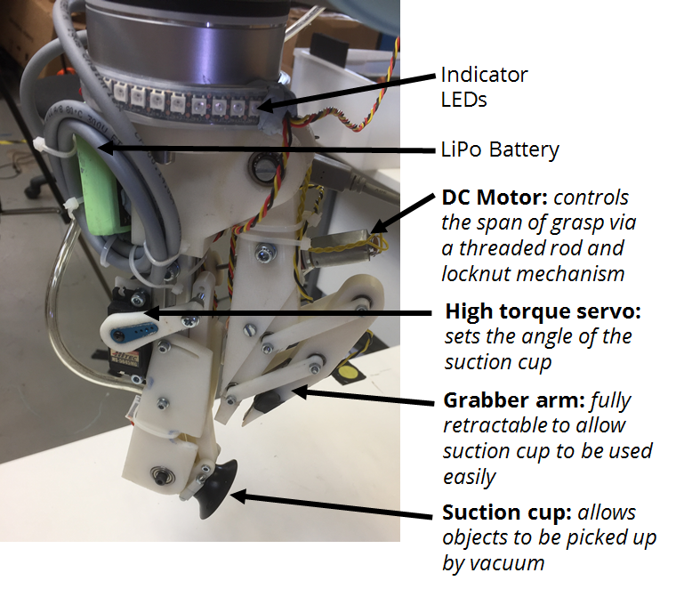
The end effector has been designed to operate in two mains modes: suction and grabbing to allow a large number of objects to be manipulated.  The gripper has three sources of actuation allowing:

  • Variation in grasping diameter
  • Variation of angle of suction head
  • Grasping arm actuation

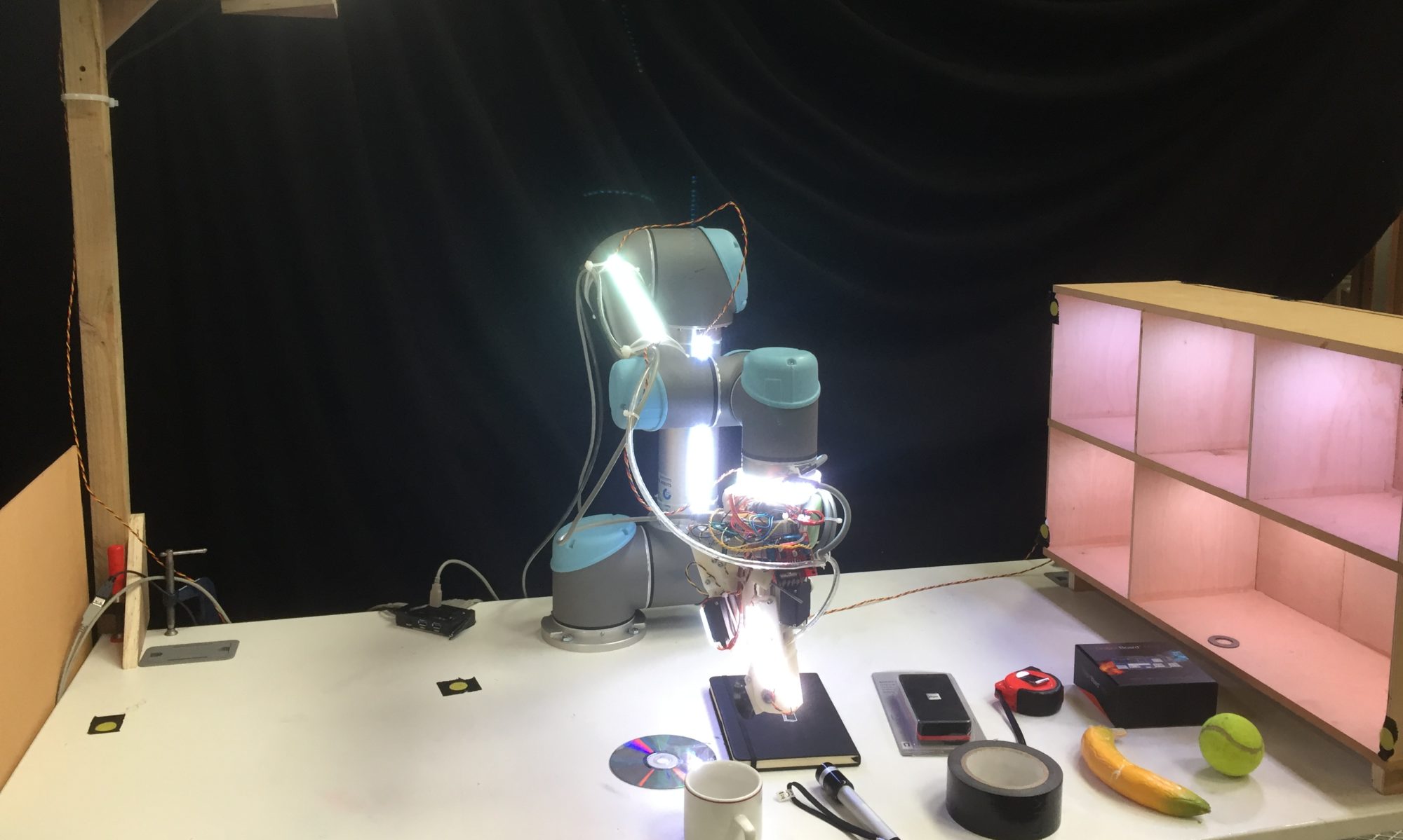
A labelled picture of the manipulator developed is shown below:

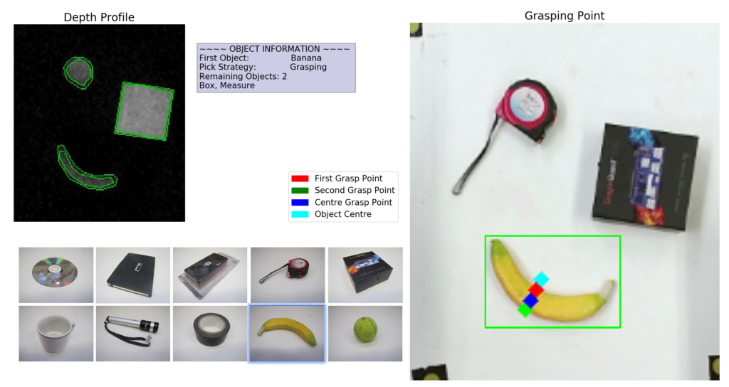
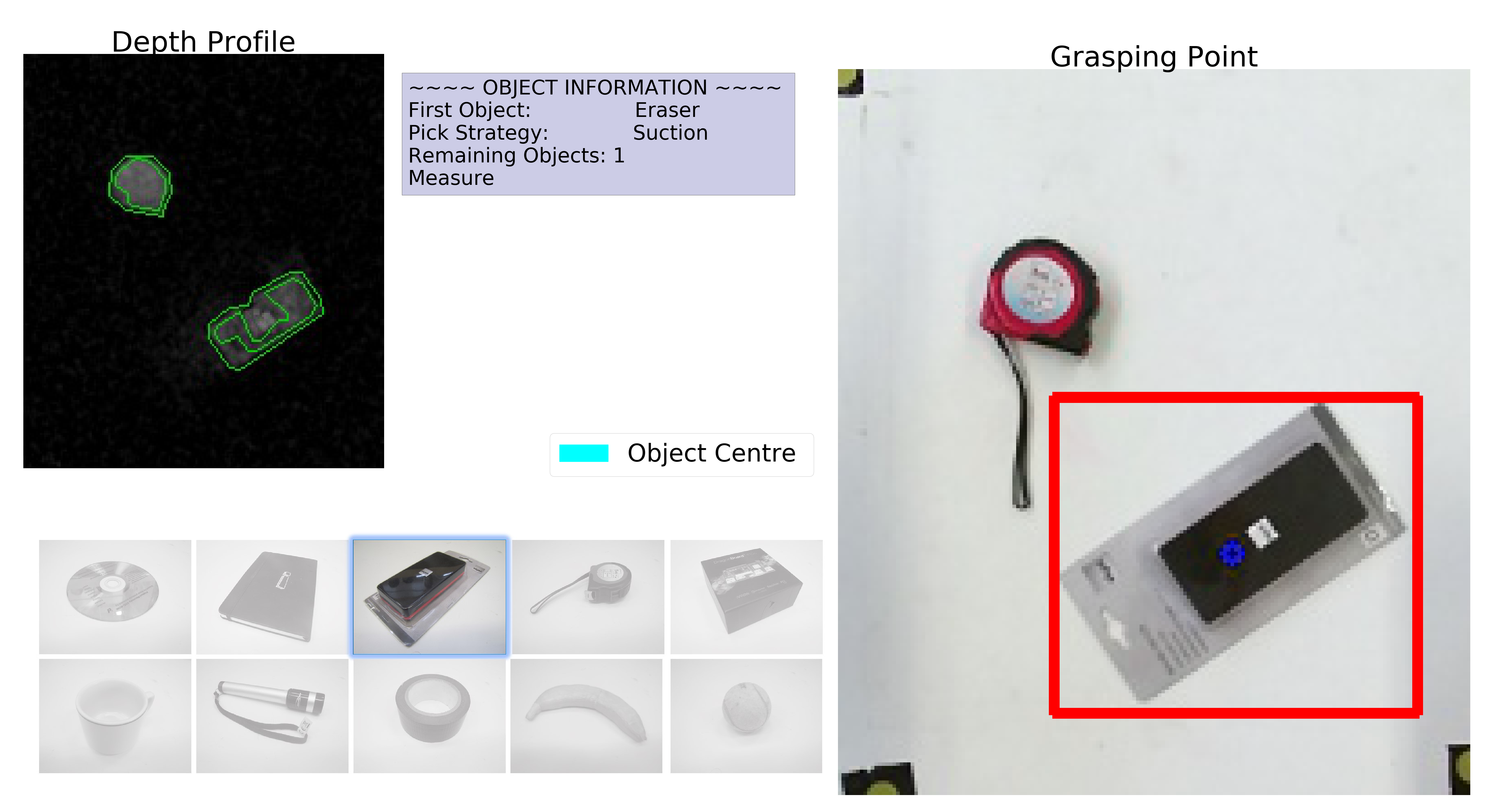
The specific grabbing strategies developed for some objects is now demonstrated.

Picking and stowing a book

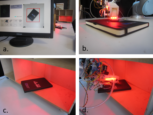
a. The suction cup is lowered in the middle of the object, b. until it is detected that the object is in contact with the suction cup, c. the object is placed on the shelf, d. suction is used in the centre of the object to pick from the shelf.

Picking and stowing a mug

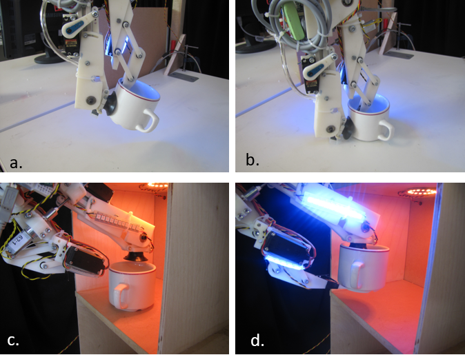
a. The cup is grasped between the suction cup and the grasping arm, b. lifted, c. placed on the shelf, d. the cup is then dragged to the front of the shelf and the manipulator arm moved underneath to cradle the mug.

Picking and Stowing the Ball

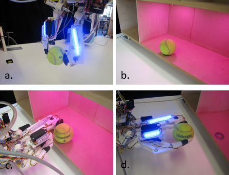
a. The ball is grasped and lifted, b. placed on shelf without rolling, c. grabber is aligned with ball, d. lifted.

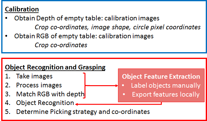
The manipulator is controlled using an Arduino, connected to valves and motors which communicates with the main PC over serial.  A block diagram of the system is shown below.

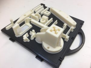
Much of the system has been produced using rapid prototyping methods allowing rapid testing and development.  The CAD files are provided in the resources section.

Using this method, we were able to develop and test a number of different manipulator solutions rapidly.

Vision

A webcam and Kinect is used for the vision system. The combined visual and depth information allows the objects to be identified and the correct grasping points identified.

The  objects are identified and the images segmented, after which the object can then be classified using a decision tree structure.  Once the object has been identified the correct grasping strategy can be applied and the optimum grasping points identified.  A summary of the algorithm developed is given below, specific details of each part are given later in this section:

The below figures shows the segment depth profile, the RGB vision shows the object identified, and bounding box applied and the grasping points determined.   Here the banana which is gripped using a grasping mechanism is shown:

A depth and RGB image for the eraser, where suction is used. this shows the object centre has been choose as the suction point.

The specific details of the Object identification algorithmn summarised above are now given:

  1. Take RGB and Depth Images
  2. Process images
    i) Crop and filter images
    ii) Zero image with empty calibration images
    iii) Extract contours using edged detection
    iv) Organise contours with respect to height and geometry
    –> Return normalised clean images and contour images
  3. Match RGB data with depth information
    create class object which extracts object features if object is detected (RGB, aspect ratio, fill, measure of how circular, etc.)
  4. Object recognition performed based on previously extracted data
    Local stored database of mapping of vision parameters to object
  5. Picking strategy determined by object recognised:
    1. Grasping algorithm
      i) First node found by closest depth contour point
      ii) Possible 2nd grasping points found by drawing perpendicular line from the 1st node
      iii) 2nd grasping point found if grasping points are at the same height and midpoint of the 1st and 2nd grasping point  is taller than the grasping point
    2. Picking
      Find centre of RGB or depth image of object (the use of which depends on which is most reliable for a given object
  6. Convert to real world coordinates
    Convert pixels to real world robot world coordinates and send the co-ordinates to the inverse kinematic solver and enable the arm movement.

Resources

The code developed can be found at our GitHub account here.

The CAD files which have been developed for the end manipulator can be found here.